
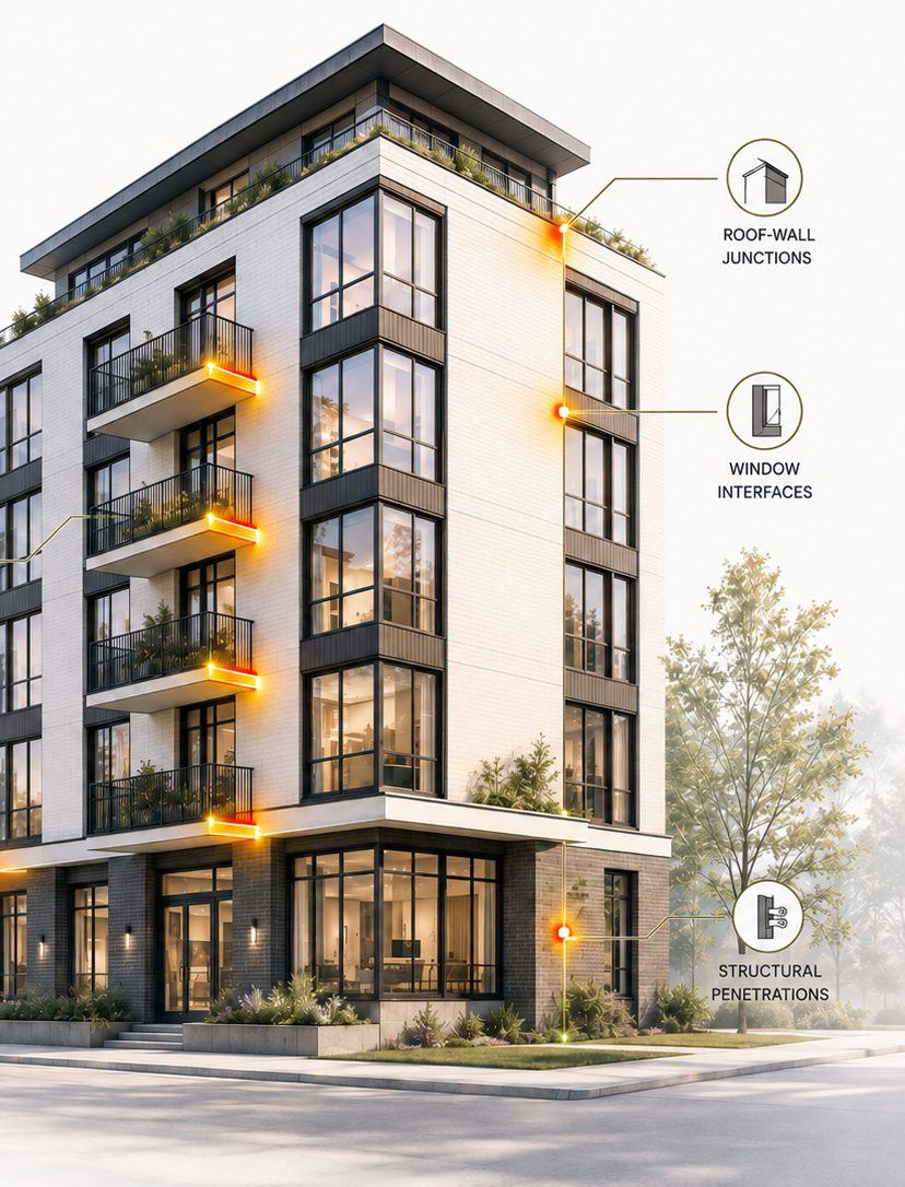
As insulation levels rise and U-values fall, heat loss through the main areas of a wall, roof or floor drops dramatically. But the weak points — slab edges, balcony connections, window perimeters, structural brackets and service penetrations — do not improve automatically. Their heat loss becomes a much larger share of what remains.
That is why thermal bridges matter more as buildings get better. In a conventional envelope, their impact can be obscured by heat loss across the rest of the enclosure. In a highly insulated building, an unresolved junction can determine whether the project achieves its intended energy performance, thermal comfort and moisture safety.
The design question is therefore not simply how much insulation a wall contains. It is whether the thermal layer remains continuous through every connection.
Better insulation makes the weak points more important. Performance is defined by the details.
What Is a Thermal Bridge?
A thermal bridge is a localised part of the building envelope where heat flow differs from — and is usually greater than — the heat flow through adjacent components. It can be caused by a break in insulation, a change in geometry, or a highly conductive material that passes through the thermal-control layer.
Steel, aluminium and reinforced concrete can create especially strong heat-flow paths when they cross insulation. The important point is not simply that these materials conduct heat well; it is that even relatively small conductive elements can bypass a large area of otherwise effective insulation.
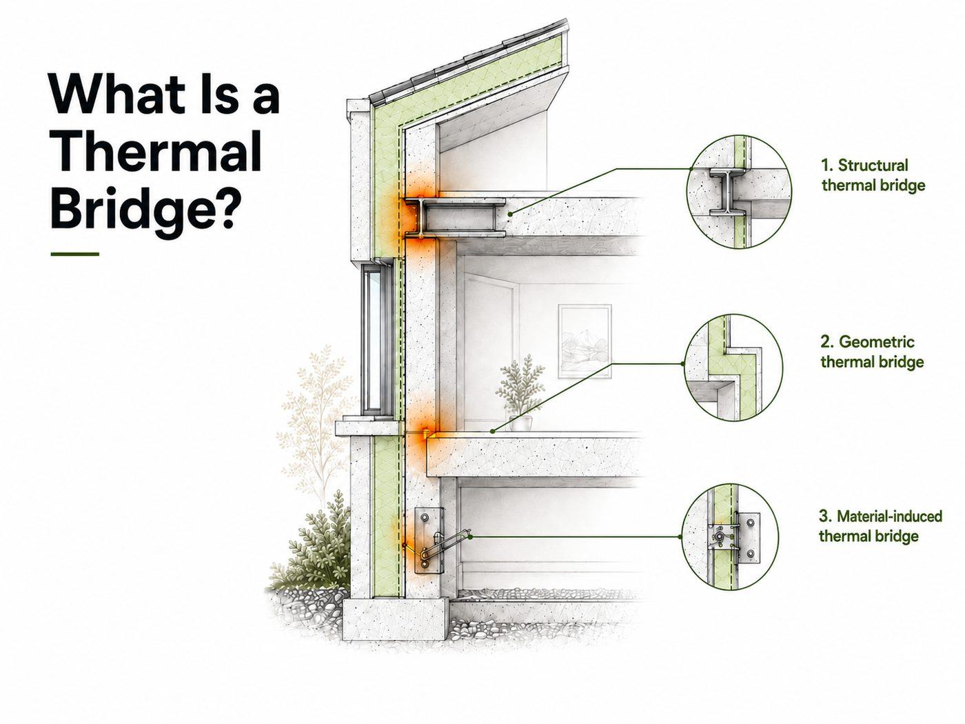
Thermal bridges generally appear in three forms:
- Structural thermal bridges: concrete slabs, steel beams, columns or other structural elements that penetrate the insulation layer.
- Geometric thermal bridges: corners, edges and junctions where geometry increases heat flow compared with the flat field of an assembly.
- Material-induced thermal bridges: fasteners, anchors, brackets, studs and other conductive materials that interrupt insulation.
Why Better Envelopes Raise the Stakes
Continuous insulation is the foundation of a high-performance envelope. It means that the thermal layer wraps the conditioned building volume without being interrupted at floors, roofs, balconies, window openings or structural transitions.
As insulation improves, heat loss through the uninterrupted, or field, area of the wall becomes much lower. The thermal bridge does not necessarily lose more heat in absolute terms, but it becomes a much larger relative source of heat loss. In other words, the baseline improves while the weak junction stays weak.
This is why simply increasing insulation thickness can produce diminishing returns if continuity is not solved at the details. A high-performance wall can still perform poorly as a whole when repeated conductive paths cut through it.
A worked example from Passive House School compares three walls, each with 200 mm of insulation:
| Wall assembly | Overall U-value, W/(m²·K) | Change from uninterrupted wall |
|---|---|---|
| Uninterrupted insulated wall | 0.18 | Baseline |
| Timber-stud wall | 0.24 | 33% increase |
| Steel-stud wall | 0.50 | 178% increase |
The lesson is straightforward: insulation thickness alone does not define envelope performance. Thermal continuity does.
Measuring Thermal Bridges
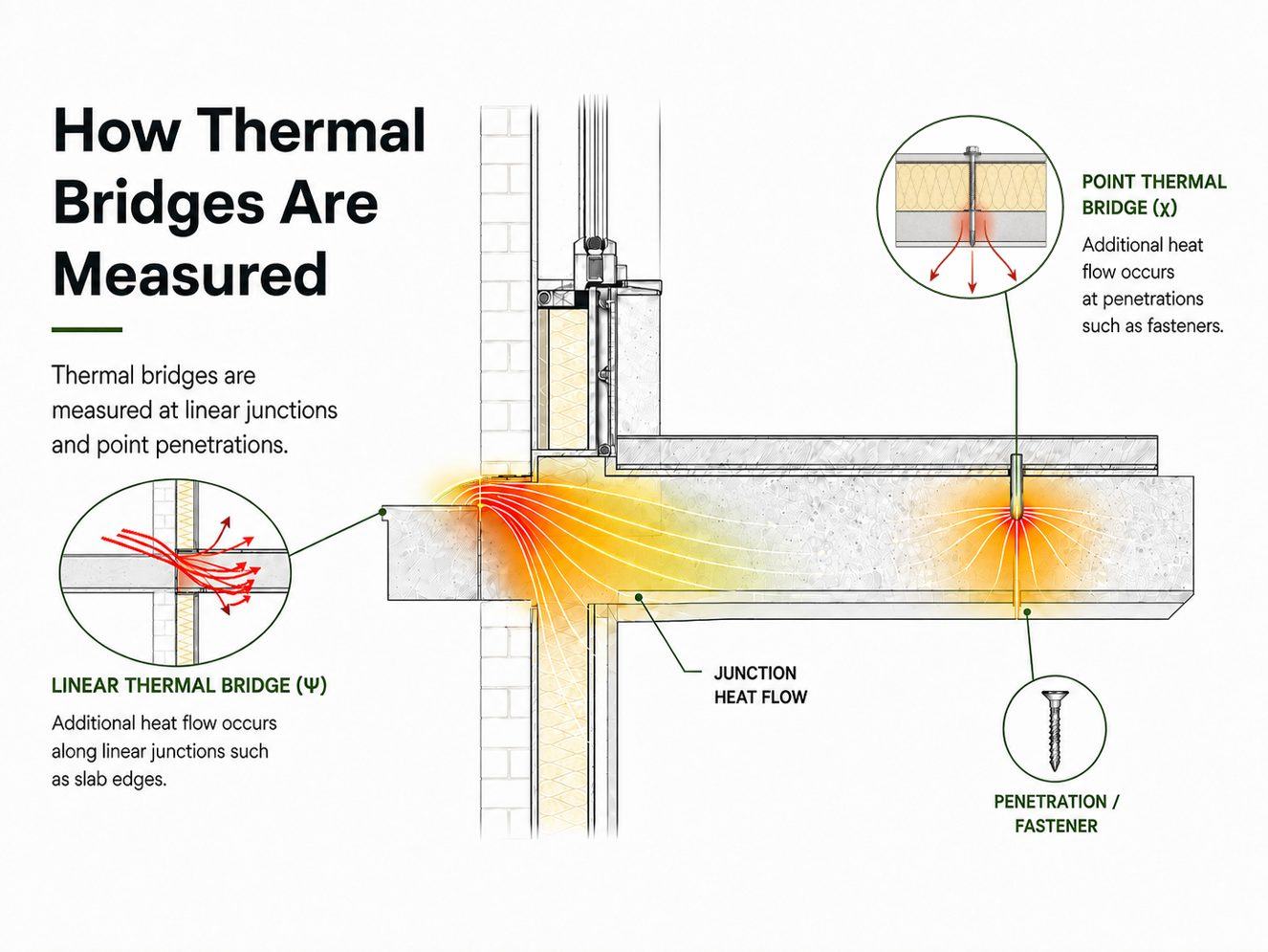
Thermal bridges are not just visible details; they can be quantified and incorporated into the building energy balance.
Psi-values (linear thermal bridges)
A linear thermal bridge is measured by its psi-value (ψ), expressed in W/(m·K). The value represents the additional heat loss along a junction relative to the adjacent undisturbed components. Typical linear junctions include:
- Wall-to-slab junctions
- Balcony connections and slab edges
- Wall-to-roof junctions
- Window heads, jambs and sills
- Foundation and floor transitions
ψ ≤ 0.01 W/(m·K) is a common Passive House rule of thumb for treating a junction as thermal-bridge-free. Where a junction is more significant, it should be modelled and its contribution included in the energy balance.
Point thermal bridges
Point thermal bridges are localised heat-flow paths measured by a point thermal transmittance, commonly represented by χ and expressed in W/K. Typical examples include canopy brackets, façade supports, insulation fasteners, anchors and service penetrations.
A single fastener may seem insignificant, but a repeated bracket or anchor condition across a façade can become a meaningful component of total heat loss. The question is therefore not only the size of the element, but its conductivity, frequency and location within the thermal layer.
Where Thermal Bridges Hide
Balconies and slab edges
A projecting concrete balcony is a classic example. When the interior floor slab continues through the façade to form the balcony, the concrete bypasses the insulation and creates a direct conductive path from inside to outside. The detail may occupy only a narrow band of the façade, but it can strongly reduce the effective performance of the surrounding wall.
The most robust strategy is to preserve thermal continuity by separating exterior structure from the conditioned structure where possible. Where a continuous cantilever is required, a structural thermal break can reduce the heat-flow path while preserving the architectural intent.
Window installation
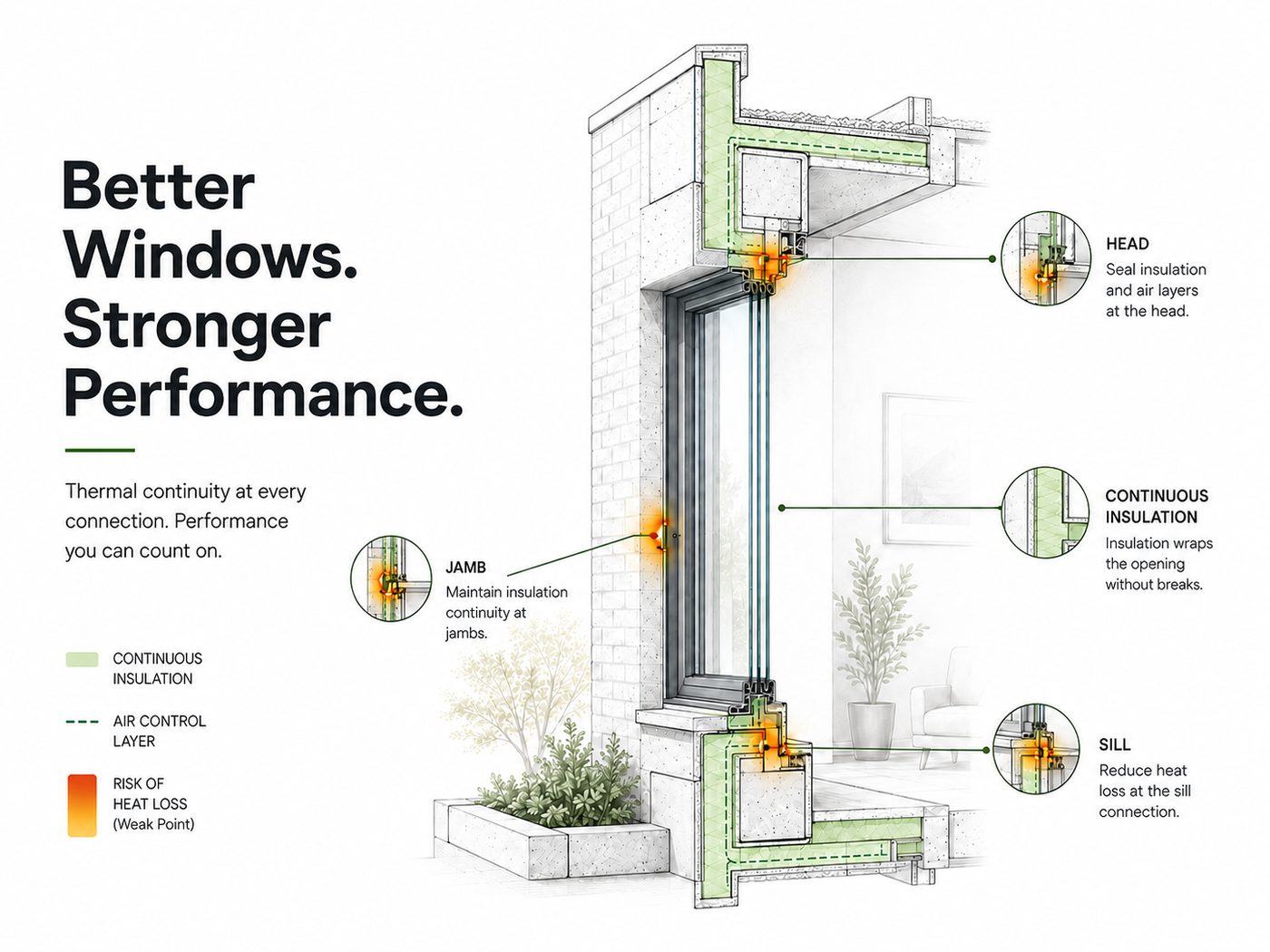
A high-performance window only performs as intended when the installation detail is equally high-performing. Frame position, insulation continuity around the opening, and the connection of air and weather-control layers all affect the junction. Heads, jambs and sills should be considered as part of the thermal design rather than treated as generic construction details.
Structural penetrations
Beams, columns, façade brackets, service pipes, anchors and fixings can interrupt continuous insulation. Good detailing asks whether the penetration can be eliminated, moved outside the thermal boundary, reduced in conductive cross-section, or isolated with a thermal break.
Thermal Bridges Affect Comfort and Moisture, Not Just Energy
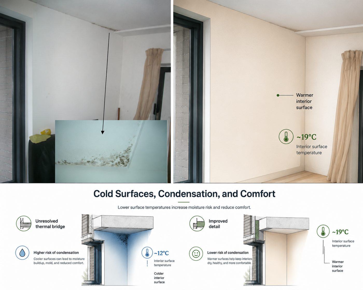
When heat escapes through a junction during winter, the interior surface temperature near that junction falls. A cold floor, wall or ceiling surface can reduce mean radiant temperature and make an occupant feel uncomfortable even when the room air temperature appears acceptable.
If the surface temperature falls below the dew point of the indoor air, surface condensation can occur. Persistently cold surfaces can also create conditions that support mould growth. The consequences extend beyond energy use to indoor air quality, durability and maintenance.
This contrast can become more pronounced in a high-performance building: the well-insulated field of the envelope stays warm, while an unresolved junction remains a localised cold spot. Better walls therefore make poor details more visible, in both the energy model and the occupied space.
Model the Junction Before It Reaches the Site
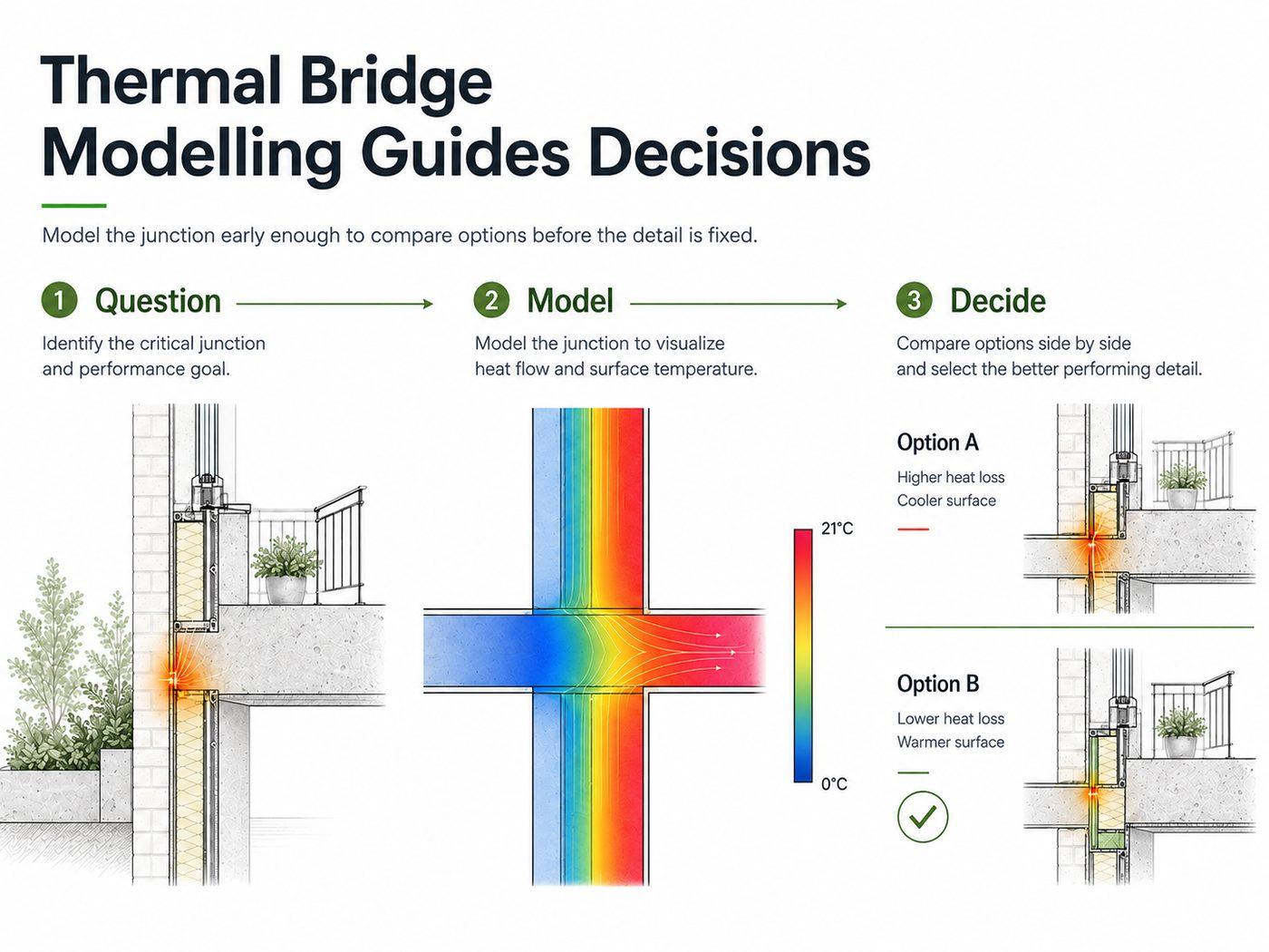
Thermal bridge modelling allows the design team to compare details before they are built. For many two-dimensional conditions — slab edges, roof-wall junctions, window interfaces and foundation transitions — tools such as THERM can visualise heat flow, calculate linear transmittance and identify cold interior surfaces. More complex three-dimensional junctions may require 3D thermal analysis.
The value of modelling is not the colour plot by itself. It is the ability to compare options: baseline detail, revised insulation continuity, structural thermal break, changed frame position or reduced conductive connection. The useful output is a design decision supported by evidence.
QuestionModelCompareDetailVerify
Case Study: Balcony Slab Thermal Breaks
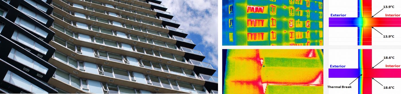
RDH Building Engineering studied exposed slab edges and projecting balconies in typical North American multi-unit residential wall systems. The work compared continuous concrete slab connections with balcony thermal-break solutions and evaluated effective thermal resistance, linear transmittance and interior surface temperatures.
The study used Heat3, a three-dimensional thermal-modelling tool validated to ISO 10211. Winter surface-temperature scenarios used 21 °C indoors and −10 °C outdoors. The comparison shows why the detail matters: a continuous concrete slab bypasses the wall insulation, while a structural thermal break interrupts that path and raises interior surface temperatures.
| Assembly | Without thermal break | With thermal break | Surface-temperature gain |
|---|---|---|---|
| Exterior-insulated wall | 13.9 °C | 18.6 °C | +4.7 °C |
| Interior-insulated wall | 8.2 °C | 15.6 °C | +7.4 °C |
The significance is not only the reduced heat flow. Warmer interior surfaces improve thermal comfort and reduce the risk of surface condensation and organic growth. The case study turns an abstract thermal-bridge discussion into a direct design decision: preserve the balcony concept, but change the way the structure crosses the thermal layer.
Real-World Detailing: Where Good Analysis Can Still Fail

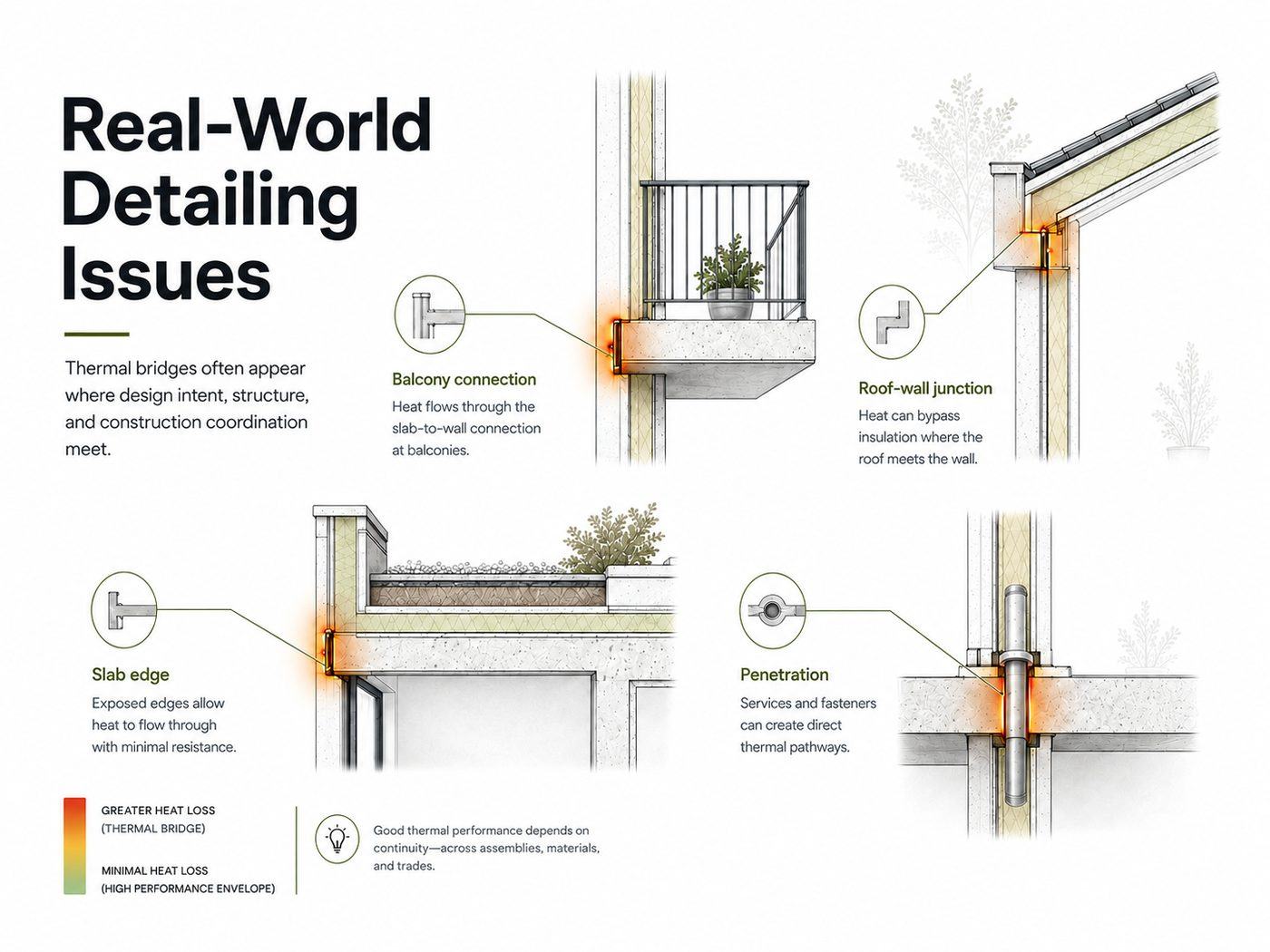
A good model does not guarantee a good building. Thermal continuity has to survive coordination, shop drawings and construction. Common failures include insulation that stops at a slab edge, a window frame installed outside the intended thermal layer, steel brackets added after the thermal study, or service penetrations that were never included in the original detail.
For the design team, this makes thermal-bridge control a coordination issue as much as a calculation issue. The architectural detail, structural connection, façade support, air barrier and installation sequence have to describe the same thermal boundary.
A practical sequence for the design team:
- Identify critical junctions early, before geometry and structure are fixed.
- Model representative and repeated details, not only unusual one-off conditions.
- Compare alternatives using both heat-loss metrics and minimum interior surface temperature.
- Carry the selected solution into drawings, specifications and shop-drawing review.
- Verify that substitutions and site changes do not reintroduce the conductive path.
The Takeaway
As buildings become better insulated, unresolved thermal bridges become increasingly important. They can undermine otherwise excellent U-values, raise heating and cooling demand, create localised cold surfaces and increase condensation and mould risk.
A high-performance envelope is therefore not defined by the insulation in the middle of a typical wall section. It is defined by the continuity of thermal control at every connection: slab edge, balcony, window, roof, foundation and structural penetration.
The best time to solve a thermal bridge is during design, before it becomes a comfort complaint, an energy-model discrepancy or an expensive construction fix.
A better envelope is not just more insulation. It is better continuity.
References
- Passive House International (iPHA) — What is a Thermal Bridge? Definition, the relative importance of thermal bridges in highly insulated construction, and the balcony-slab example.
- RDH Building Engineering Ltd. The Importance of Slab Edge & Balcony Thermal Bridges, Report #2: Impact of Slab Thermal Breaks on Thermal Comfort and Condensation Control. 24 September 2013. Source of the Heat3 methodology and interior surface temperatures.
- Passive House School — The Science Behind Thermal Bridges and How to Avoid Them. Thermal-bridge categories, ψ-values, point bridges and the worked wall example.