

When building envelope performance is discussed, the conversation often starts — and ends — with one metric: U-factor.
A lower U-factor is generally better at reducing conductive heat transfer. But a building does not experience heat transfer through walls alone. Windows admit solar radiation. Shading changes those gains. Air leakage affects heating and cooling loads. Thermal bridges can reduce the real performance of insulated assemblies. And the same envelope strategy can perform very differently depending on climate and orientation.
That is why ASHRAE 90.1 envelope modelling requires a much broader view.
Start With Climate, Not Construction
Before selecting an insulation value or glazing property, the modeller needs to establish the project’s climate zone and space-conditioning category.
ASHRAE 90.1-2016 uses Climate Zones 0 through 8, with moisture regimes where applicable. The climate zone determines which envelope requirements apply to the project. But there is an important distinction:
Climate Zone ≠ Weather File
The climate zone is a code classification used to select requirements. The weather file provides the hourly outdoor conditions used by the simulation engine. They should correspond to the same project location, but they serve different purposes and should be documented separately.
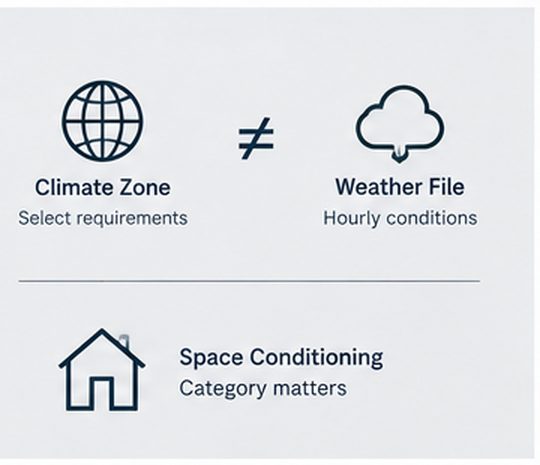
The next question is equally important: what type of space does the envelope enclose? The applicable requirements can differ depending on whether the space is nonresidential, residential, semiheated or unconditioned. So the correct sequence is:
Location → Climate Zone → Conditioning Category → Envelope Requirements
Not: wall assembly → pick a U-factor.
U-Factor Is Only One Part of the Wall
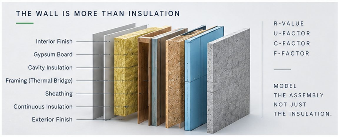
For opaque assemblies, ASHRAE 90.1-2016 uses different thermal metrics depending on construction type, including R-value, U-factor, C-factor and F-factor. These metrics are not interchangeable:
- An insulation R-value describes thermal resistance.
- A U-factor describes the thermal transmittance of an assembly.
- C-factor is used for certain below-grade wall conditions.
- F-factor is associated with slab-on-grade perimeter heat flow.
Perhaps the most common modelling mistake is assuming that the nominal insulation value is the same as the performance of the completed wall. It is not. A wall containing cavity insulation also contains framing and other heat-flow paths. Continuous insulation can reduce the effect of repetitive thermal bridging, while the complete assembly may perform differently from the insulation layer alone.
Model the assembly — not just the insulation.
For roofs, insulation is only part of the envelope input. Under the 2016 prescriptive provisions, solar reflectance and thermal emittance can also affect the requirements and the modelled solar heat gain.
Windows Change the Equation
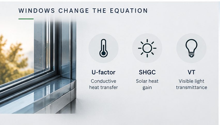
Once glazing enters the façade, the envelope becomes much more than a conductive barrier. Three properties become particularly important:
| Property | What it represents | Typical modelling effect |
|---|---|---|
| U-factor | Conductive heat transfer through the fenestration product | Lower values reduce heat transfer |
| SHGC | Solar heat admitted through glazing | Lower values reduce admitted solar heat; suitability depends on climate and orientation |
| VT | Visible light transmitted through glazing | Higher values can support daylighting |
Use whole-product fenestration values when required. Centre-of-glass values do not include the effects of frames and spacers, and should not be substituted when the compliance method requires whole-product performance.
WWR Is Not Just an Architectural Number
The window-to-wall ratio (WWR) is a significant envelope input in an energy model. It is calculated as:
WWR = Vertical Fenestration Area ÷ Gross Above-Grade Wall Area
The denominator is the gross wall area, not the remaining opaque wall area. That sounds straightforward, but a small error can be repeated across a large façade and materially affect the model.
More importantly, whole-building WWR is not always enough. Orientation matters. A building with the same total WWR can behave very differently if most of its glazing is concentrated on the east and west façades. That is why the envelope input record should distinguish north, east, south and west wall and fenestration areas, along with WWR, U-factor, SHGC and shading.
40% glazing is not one condition.
Forty percent north-facing glazing and forty percent west-facing glazing can produce very different solar and cooling behaviour.
Shading Is Part of the Envelope
Glazing properties are only part of solar control. Overhangs, fins, neighbouring structures and self-shading can materially change the amount of solar radiation reaching the façade.
In prescriptive compliance, only qualifying permanent projections can be used, and only in the specific way the standard permits. In performance modelling, proposed and comparison-model shading must follow the rules of the selected method.
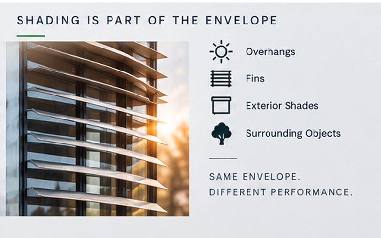
Shading should not be treated as an afterthought, added to the model simply because it exists in the architectural drawings. Its geometry and treatment need to be represented consistently with the compliance method.
Air Leakage: The Invisible Part of the Envelope
A well-insulated building can still perform poorly if uncontrolled airflow is not addressed. This is where air barriers and infiltration need to be distinguished:
- An air barrier is a physical system intended to limit uncontrolled airflow through the envelope.
- Infiltration is the simulation’s representation of that uncontrolled airflow.
They are related, but they are not the same thing. The air barrier should form a continuous enclosure across transitions between walls, roofs, floors, foundations, windows, doors and service penetrations.
For energy modelling, infiltration assumptions also need a defensible basis. An undocumented infiltration rate can significantly affect heating, cooling and humidity results. So when documenting infiltration, the question should not simply be “What number should I enter?” It should be:
What evidence supports this assumption?
Proposed ≠ Budget ≠ Baseline
There is one final complication that matters greatly for energy modellers: the envelope is not necessarily represented identically in every model.
- The Proposed Building Design represents the actual project.
- The Section 11 Budget Building Design follows Section 11 rules.
- The Appendix G Baseline Building Design follows Appendix G rules.
These are different modelling frameworks, so envelope inputs should not simply be copied from one model to another (see Part 3, Budget Building vs. Baseline Building). For example, the Appendix G baseline does not simply mean “use 40% glazing everywhere.” In the 2016 methodology, baseline vertical-fenestration percentages are tied to the applicable building area type and rules.
The comparison model is therefore a rule-defined model — not a generic “code-minimum façade.”
Common Misconceptions
- “A higher R-value automatically means a better modelled wall.”
- Not necessarily. Assembly performance also depends on framing, thermal bridges and the applicable construction method.
- “Lower SHGC is always better.”
- Not automatically. Climate, orientation, heating, cooling, daylight, glare and operation all matter.
- “WWR is just the percentage of opaque wall replaced by glass.”
- No. WWR uses the gross above-grade wall area as the denominator.
- “Air leakage is just another infiltration schedule.”
- No. The air barrier is a physical envelope strategy; infiltration is its representation in the simulation.
- “The Appendix G baseline always uses 40% glazing.”
- Not in the 90.1-2016 methodology. The applicable baseline rules depend on building area type.
The Real Insight
The biggest mistake in envelope modelling is treating the façade as a collection of independent numbers:
- U-factor affects heat transfer.
- SHGC affects solar gain.
- VT affects daylight.
- WWR affects the amount of glazing.
- Shading modifies solar exposure.
- Air leakage affects uncontrolled airflow.
- Thermal bridges influence real assembly performance.
And all of them interact with climate, orientation, internal loads, HVAC systems and building operation. That is why a strong envelope model does not begin with “What is the U-factor?” It begins with:
How does this envelope actually behave as a system?
The real shift is from modelling materials to modelling performance.